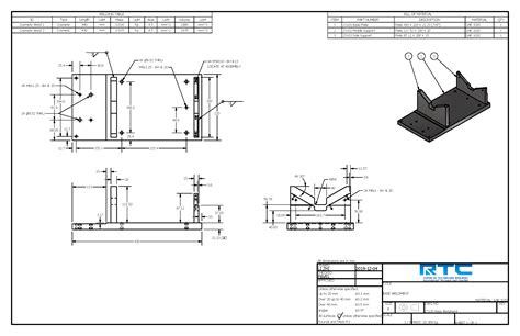
sheet metal welding drawing The welding symbol is a graphical representation that is used to give the design requirements to the shop in a concise manner. For E.g. a symbol can be used to specify the . Buy ZINUS 5 Inch Metal Smart Box Spring / Mattress Foundation / Strong Metal Frame / Easy Assembly, King: Box Springs - Amazon.com FREE .
0 · weldment drawing examples
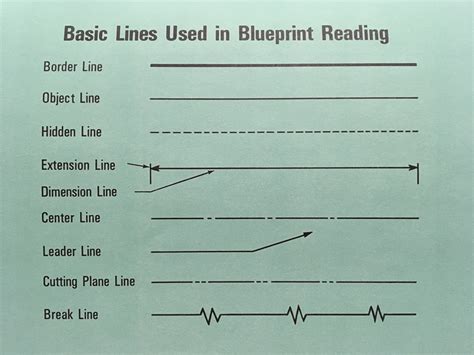
1 · welding blueprint lines and symbols
2 · weld symbol cheat sheet pdf
3 · weld specifications on drawings
4 · printable weld symbol chart
5 · laser weld symbol on drawing
6 · images to draw for welding
7 · drawing weld symbols chart
Metalworking recipes involve crafting with metal, whether it be crafting items, or constructing buildings and furniture. Crafting gear Tools

Learn welding symbols easily with our in-depth guide, featuring detailed charts, drawings, explanations and real examples.Interpreting metal fab drawings is a course that introduces the principles of interpretation and application of industrial fabrication drawings. Basic principles and techniques of metal . The welding symbol is a graphical representation that is used to give the design requirements to the shop in a concise manner. For E.g. a symbol can be used to specify the .
When there is no side significance this can commonly be applied using a resistance spot welder which is used widely in sheet metal work. A spot weld is simple a weld applied to the surface of one member that has enough heat .Welding Symbols can be used when producing drawings for your metal fabrication. It is important for us to understand what weld detail is important to you for your fabrication design. Simply saying weld here or corners to be welded . Two-dimensional (2D) drawings are fundamental in the sheet metal fabrication sector. These drawings are graphical representations of the final product, carrying comprehensive details about dimensions, material specifics, .
This article will provide a series of key sheet metal design and fabrication guidelines to help engineers and designers understand how to maximize the use of the characteristics of metal sheets, ensuring the feasibility . This includes details about the type of weld, its size, its location, and more. In this in-depth guide, we’ll take a close look at different types of welding symbols and what they mean. By the end, you’ll have a .
As stated earlier, Weld Symbol is a term used explicitly to designate a specific type of weld.The pertinent types of welds considered under the governing AWS A 2.4 specification for ‘Symbols for welding, brazing and . Sheet metal fabrication is a comprehensive cold-working process for thin metal sheets, typically less than 6 mm in thickness. This versatile manufacturing method encompasses a wide range of operations, including . AWS D9.1/D9.1M:2018 – Sheet Metal Welding Code: This specific code addresses the arc and braze welding requirements for nonstructural sheet metal fabrications. It encompasses commonly welded metals available in .
weldment drawing examples
Sheet Metal and Welding Quiz. What happens to the thickness of sheet metal as you go from 8 gauge to 22 gauge? Identify 2 methods of showing sheet metal parts on a mechanical drawing. Identify 2 methods of dimensioning features on a sheet metal part. Define bend allowance and identify 3 factors that impact the amount of bend allowance presence. weld within a part (or sheet metal part). As previously stated: - open a new/empty weldment.iam file - place your sheet metal file - place the welds required to close your corners - save the weldment.iam - make a drawing of the weldment showing the beads with callouts - create any flat pattern drawings from the original sheet metal file-- Gary .The factory has an area of about 8,200 squar e meters and is a professional precision sheet metal origin manufacturer, providing customers with a full set of latest automated sheet metal production solutions that integrate Precision Laser Cutting, Fiber Cutting, CNC Robot Bending, Riveting, Welding, Broaching, Drilling, Tapping, Notching . I was not paying attention to the thickness of sheet you were specifying .9 of a mm is equivalent to 20gauge sheet metal. In normal industrial practice it is more common to put a spot welded tab flange with a sealant, rather than a weld. If you insist on torch welding this part (TIG) heliarc is recommended.
Download a PDF of the paper titled Cyclegan Network for Sheet Metal Welding Drawing Translation, by Zhiwei Song and 3 other authors. Download PDF Abstract: In intelligent manufacturing, the quality of machine translation engineering drawings will directly affect its manufacturing accuracy. Currently, most of the work is manually translated .Position the two metal pieces in the desired arrangement, taking into consideration the welding joint and the orientation of the pieces. Use the "Weldment" feature in SolidWorks to create a weld bead between the two metal pieces. This can be done by selecting the edges or faces of the metal pieces where the weld bead is required.
SHEET METAL WELDING GUIDE . Updated figures and drawings of typ-ical welded joint designs. New guidelines for developing welding procedures are provided in the chapter on standards, codes and specifications. Estimating is expanded and provides both a short and long method of estimating welding costs with ex-
An automatic translation method for welded structural engineering drawings based on Cyclic Generative Adversarial Networks (CycleGAN), which meets the welding engineering precision standard and solves the main problem of low drawing recognition efficiency in the welding manufacturing process. In intelligent manufacturing, the quality of machine translation .Deep Drawing Process Prepare the Sheet Metal. The preparation of the metal sheet is a crucial step to take before diving into the deep drawing. . We specialize in sheet metal laser cutting, bending, surface finish, and sheet metal welding. We place a high priority on establishing trust, maintaining standards of quality, providing competitive .Aug 6, 2021 - Explore Keane Low's board "Sheet metal Template drawing" on Pinterest. See more ideas about sheet metal, metal working, mechanical design.
sheet metal parts in the manufacturing process of heavy industry equipment is manual recognition of engineering drawings[1,2]-manual redrawing of specific graphics[3,4]-sheet metal cutting and stamping based on CAD/CAM integrated system[5,6,7]. The process of obtaining specific sheet metal parts in traditional ways isI typically use one drawing per individual sheet metal part, and if it is welded that is treated as one weldment part. The individual sheet metal parts are inserted into the weldment part. However, if the weldment contains extrusions then those compoments are all created inside the weldment due to the ease of generating a cut list, creating .
presented in Table 1. The top sheet metal is the 6013-T6 aluminum alloy, and the bottom sheet metal is the 2029-T8 aluminum alloy. The top sheet metal is refill friction stir spot welded onto the bottom sheet metal using the robotic RFSSW system in Figure 1. The configuration of the sheet metal panel is depicted in Figure 2. The panel clamping .Discover the essentials of Sheet Metal Tolerances with our in-depth guide covering dimensional, geometric, and material variations. . It is essential to communicate the tolerance requirements on engineering drawings. Including .
welding blueprint lines and symbols
Setelah mendaftar dan menyelesaikan kursus ini kamu akan menguasai 4 materi utama antara lain : 1. 3D Sheet Metal Modeling 2. 3D Frame & Chasis Modeling 3. 3D Welding Modeling 4. 2D Drawing Sheet Metal, Frame & Welding A stitch weld or Intermittent weld consists of a weld symbol (e.g. a filet weld in the below example), weld size, length of the weld (e.g. 2 inches), and the pitch (6 inches in the below example). Stich Welding is Also called Skip welding and they are mainly used to control the welding distortion, especially in sheet metal welding. Sheet metal shop drawings are blueprints for metal fabricators that play a central role in aligning the shop floor operations with the design intent. Detailed shop drawings not only streamline the fabrication process but also mitigate costly errors, delays, and reworks and ensure that every piece fits seamlessly into the larger assembly. Discover the top 5 free CAD software for sheet metal design, including FreeCAD, Onshape, and Fusion 360. Unleash your creativity with these powerful, easy-to-use programs that streamline your sheet metal projects. . (2D). With QCAD you can create technical drawings such as plans for buildings, interiors, mechanical parts or schematics and .
2024/03/04 - 23K Followers, 835 Following, 207 Posts - DIY Welding Projects 🔧 (@ta6urkin) on Instagram: "I am a design engineer, I create drawings (not a welder) MY PROJECTS STORE ↓" . DIY Welding Projects Plans Drawings Idea Sheet Metal Work Dog Pattern Template Sculpture Plasma DXF. Craftsman: [email protected]. Link to projects . By utilizing sheet metal detailed drawings and advanced CAD-CAM technology, fabricators can compete more effectively and stay responsive to market needs. . Drawing must clearly mark weld locations, welding types and lengths; See below for example of typical details included in sheet metal part drawings: Know the optimal level of detailing forEdge weld symbols are most commonly associated with sheet metal or “gauge” material. This gauge is a system used in order to call out sheet metal similar to that of electricians and wire. This chart can range from the largest gauge of carbon steel at #7 which is a decimal of .1793” all the way to the smallest which is #28 at a decimal of .

Hi, I am completing a sheet metal design that requires welding to fasten the design at its four corners (the shape is basically a rectangular box) Two things I am noticing is that Fusion 360 doesnt seem to have bend rules properly suited to making a design that's weldable, and also you can annotate welds in drawings. Can someone help with work arounds for both .Sheet metal joinery uses welding metal ____ inches or less in thickness. 3/16 ____ lines may also be applied to a detail drawing to indicate lengths to be welded. Hatching. When specifying the length and spacing of intermittent edge welds, the dimensions are placed to .Drawing shapes Drawing Radii - 2 - . Critical Dimensions Sheet Metal Forming – Outside dimension should be used unless the inside dimension is critical. . lances, half-shears, and weld projections. Virtually any form can be made as long as it falls within the following constraints. The form depth must be less than 5/16" and it must fit .
sheet metal fabricators new york ny
sheet metal fabricators surrey
Zinc Sheet .060" thickness or 15 gauge. These sheets are GRADE B and are .
sheet metal welding drawing|weld symbol cheat sheet pdf