sheet metal corner relief size Generally capabilities of of 0,9mm – 20mm in thickness are able to be manufactured from sheet (3mm) but this tolerance depends mainly on the part. When considering sheet metal thickness, a single sheet . Here is the list of the 11 best permanent fabric glues that you can use to craft, mend, and repair your favorite fabrics. 1. Aleene’s 25042 Fabric Fusion - Best for Flexible Wear. One .
0 · solidworks sheet metal relief cut
1 · solidworks sheet metal corner treatment
2 · solidworks sheet metal corner relief
3 · solidworks sheet metal corner
4 · solidworks sheet metal bend relief
5 · sheet metal corner relief chart
6 · sheet metal bending chart
7 · auto relief solidworks sheet metal
What is CNC: CNC stands for computer numerical control, which is a process of using computer software to control the movement and operation of machines that can cut, carve, or engrave materials. Types of CNC machines : There are different types of CNC machines, such as routers, mills, lathes, lasers, and plasma cutters.
The article discusses making small holes and when to use a punch or laser cutter, inside radius measurements and how they differ depending on whether you are coining or air bending on a press brake, and adding bend . With a 90-degree bend, the equation for your bend relief should be: Material Thickness + Bend Radius = Bend Relief, or, 0.10 in (2.54mm) + 0.030 in. (0.762mm) = 0.13 in. (3.302mm). This tiny adjustment to your CAD .
Bend relief is provided at the end of the bending edge in sheet metal design to avoid any crack tearing in the corner. Recommended Bend Relief height is always more than two times of .Generally capabilities of of 0,9mm – 20mm in thickness are able to be manufactured from sheet (<3mm) or plate (>3mm) but this tolerance depends mainly on the part. When considering sheet metal thickness, a single sheet .
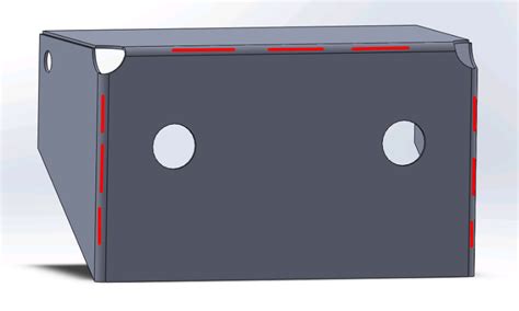
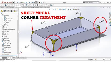
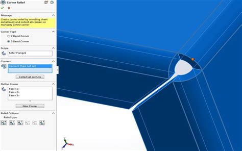
Corner Relief Size For a 2 bend intersection such as a Square or Round. When any two flanges or Contour Flanges meet at a 2 Bend corner, a parameter called CornerReliefSize is applied.Sheet metal fabrication is the process of forming parts from a metal sheet by punching, cutting, stamping, and bending. 3D CAD files are converted into machine code, which controls a .Sheet Metal Style parameters such as miter gap or relief shape applies to all corners. This new capability helps to streamline certain operations as well as simplifying the browser structure for .You can add a corner relief to a single sheet metal body. Use the Corner Relief PropertyManager to apply corner treatments to a folded sheet metal body that persist in the flattened state. .
Learn the crucial sheet metal bend relief rules for smooth fabrication and Essential sheet metal bend relief guidelines. Expert tips for your successful projects.
To modify a corner on a sheet metal model: While in a Part Studio with an existing sheet metal model, tap . Select an edge, vertex, or face of a corner on the sheet metal model in the graphics area. Select the type of corner relief: Square - Sized. Flat view: 3D view:
The Add Corner Relief button. The SheetMetal → Add Corner Relief menu option. The keyboard shortcut: C then R. Relief shapes. The shape of a corner relief can be altered by changing its property values: The value of . But I have the (3) flanges, 2 on the sides and a long one in the back. Then added corner seams between the long and sides to set and equal gap, but this pulls the corner style from the sheet metal defaults. With the hem .The type and dimensions of corner reliefs are very much design dependent and can be freely chosen. But be aware that the size of a corner relief must be big enough to completely separate the two (or more) affected bend zones, so that they don't touch each other (except in one single vertex on the sheet). Bend Relief. Synchronous sheet metal is pretty cool, even cooler than just normal synchronous modeling, if you’ll excuse that word. . To get a corner relief, you’ve got to have a corner. A corner is created by the intersection of 3 orthogonal faces. Corners. . Notice that the flat pattern itself gives you a dotted sheet size, with blank .
About Press Copyright Contact us Creators Advertise Developers Terms Privacy Policy & Safety How YouTube works Test new features NFL Sunday Ticket Press Copyright .Sheet Metal Corner Treatment . There should be an option called "corner relief" or similar. Looks like yours is set to rectangular. Try some of the other options until you find the one that gives you the desired geometry. . Top 2% Rank by size . More posts you may like r/SolidWorks. r/SolidWorks. ALL posts related to SOLIDWORKS are welcome. The value of the Relief Ratio must be between 0.05 and 2.0. The higher the value, the larger the size of the relief cut added during insertion of bends. . The Auto Relief settings do not have any impact on the corner treatment of the sheet metal part. Corner Relief.In the Design workspace, on the Sheet Metal tab, the edit rule and new rule dialog allow for customizing specific sheet metal features. . Round: The size of a round corner relief is the radius of the cutout. Square: The size of a square corner relief is width of the square cut out.
The corner relief function only looks for places where 3 faces come together. Is there an option to add a cutout along a normal bend? Basically when I bend the metal a bump comes up at the bend, so I want to add a shallow cut at all the bends to allow for a completely flat face.Use the Corner Relief tool to add relief to one or more corners of a sheet metal part. When you add relief, sheet metal sections are removed from the model. You can apply corner relief automatically to all corners or manually to individual sets of corners. Relief helps to control sheet metal material behavior and to prevent unwanted deformation .Sheet Metal Style Creation: This sample illustrates creating a new sheet metal style. It uses a bend table and assumes the sample bend table delivered with Inventor is available. You can edit the path below to reference any existing bend table. To use the sample make sure a bend table is available at the specified path, open a sheet metal .

Adding a Corner Relief. You can add a corner relief to a single sheet metal body. Corner Relief PropertyManager. Use the Corner Relief PropertyManager to apply corner treatments to a folded sheet metal body that persist in the flattened state.I am new to sheet metal, and am trying to model foam as a sheet metal. I made a new rule based on steel and changed its thickness to 0.5 inches, and its k-factor to 0.0296 based on research I found. But the flanges that bend towards each other never want to be snug.It shouldn't be a problem. You can edit the flat pattern feature properties and try toggling the corner treatment setting. You can also add corner trims to the flat by hitting the flatten button then going to Insert > sheet metal > corner trim. This .
Hi, i'm trying to add corner reliefs to the sheet metal part, but it gives me this type of result where the edge has little crack on it. . The basic problem is that the size of the relief is too small. The "Centered on bend lines" and "Tangent to bend" .Use the Edit Corner Relief tool to edit existing corner reliefs or introduce new corner reliefs by selecting relevant geometry in your model. When you edit corner reliefs, you can change the width and depth of different types of reliefs and .
solidworks sheet metal relief cut
solidworks sheet metal corner treatment
Plasma cutting bend relief cuts for hand bending sheet metal. I'm an absolute 100% newbie to CNC plasma cutting, CAD, and solidworks. I tried Freecad, and Fusion 360, but Solidworks feels like it has just "clicked" for me, particularly with 3D parts, which is what most of my needs are. . There is an auto corner relief tool, but it will only .
Sheet Metal Corner Relief example files? Sorry for two posts in one day. I’m trying to generate sheet metal corner reliefs in Fusion that have the minimal amount of ‘white space’ in the corners. I’ve managed to do Square and Round corners, but you can see from the SeeCutSend pic of SolidWorks examples - these have the most whitespace in .Corner relief is for controlling if/how material is removed from the base flange where two or three corners come together. Removing material here can make a part easier to bend accurately. . Searching YouTube for "solidworks sheet metal corners" or a specific feature name will get you a bunch of results. Reply reply Top 2% Rank by size . More .

solidworks sheet metal corner relief
It seems that the bend down is along the whole face which creates the relief on the corner in solidworks where as the original you are copying, the bend is actually away from the corner by a few mm. Seeing that your bend is also offset from the Face ID say shorten the extended section to bring the bend away from the corner and it should solve this
solidworks sheet metal corner
Saved searches Use saved searches to filter your results more quickly To modify a corner on a sheet metal model: While in a Part Studio with an existing sheet metal model, tap . Select an edge, vertex, or face of a corner on the sheet metal model in the graphics area. Select the type of corner relief: Square - Sized. Flat view: 3D view:Corner defaults are specified in the Sheet Metal Style. Corner defaults are enabled when more than one flange is being created in the same feature. This enables a smooth workflow where the flange requirements are completely defined in one pass. . Sets the relief size for the selected corner. Uses the default size defined in the sheet metal . Change to the size you need it to be. I have as .1 to get the corner seam as close as it can be. . In the corner tab. Open sheet metal defaults, select the corner tab. Then select the corner relief shape you want from the drop down menu i have circled in the print screen below. Any problems or question i will be happy to help.
I've got a sheet metal part that I want to break the sharp corners of, using the break-corner/corner trim tool. When I select the face, All of the external corners get picked up automatically except one (see screenshot below). Even if I start a new break corner feature an try to select this corner manually, I can't get it to pick it up.
solidworks sheet metal bend relief
Sheet Metal Design: Understanding Corner Relief Design Flexibility 2 The contour flange is created using the auto-miter option, and the seven-edge loop of the polygon is selected. The resulting model faces are all nicely trimmed and all have appropriate corner relief in the flat pattern. Figure 3 Figure 4 Figure 5 Figure 6

Garage cabinets can be made out of plastic, wood, aluminum, and stainless steel. Plastic garage cabinets are durable, waterproof, and lightweight, making them a great option .
sheet metal corner relief size|solidworks sheet metal corner relief